Nonblocking vs. Blocking Assignments in Verilog
 Matei Barbu published on
Originally published in my digital-computers-1 repository, where you can also find the testbench, the Makefile and the Yosys script.
Nonblocking vs. blocking assignments
Table of Contents
Created by gh-md-toc
Introduction
You may have heard that the difference between = and <= in Verilog is that = assignments are executed sequentially and <= in parallel. However, this is only from a “users perspective” (see 3). So in this post we will be diving deeper in order to understand the difference between the two.
Thinking in Verilog
In Verilog we think in maybe three different ways:
- Simulation thinking
- FPGA thinking
- ASIC thinking
The first mindset is based on event driven simulation. To dismiss any event driven simulation confusion read this link 1.
The second and third ones must be discussed in parallel. When we think about code that is going to be run on an FPGA or turned into a ASIC, what we are conceptualizing is synthesizable code, that is code that could be turned into hardware.
A ASIC is composed out of the logic gates, which are interconnected by the netlist generated in the synthesis step of any HDL toolchain.
A FPGA is more complicated on the other hand, it is build out of Lookup Tables. So, combinational logic is generally synthesized using flip-flops or latches and the internal clock network.
Assignments in Verilog
It is generally now that one who seeks to understand what Verilog code means learns about the difference between nonblocking and blocking assignments.
As I learned from this link 2, nonblocking assignments are the first step Verilog developers took to solve non-determinism.
Why do you need to care? Because an excellent article published by Cummings (see 3) shows us that running the same code in different conditions yields different results. (I would like to note that MIT course 6.111 take very seriously the guidelines in the former article.)
As the author writes:
A blocking assignment gets its name because a blocking assignment must evaluate the RHS arguments and complete the assignment without interruption from any other Verilog statement.
A nonblocking assignment gets its name because the assignment evaluates the RHS expression of a nonblocking statement at the beginning of a time step and schedules the LHS update to take place at the end of the time step.
And he advises us to use these guidelines:
- When modeling sequential logic, use nonblocking assignments.
- When modeling latches, use nonblocking assignments.
- When modeling combinational logic with an always block, use blocking assignments.
- When modeling both sequential and “combinational” logic within the same always block, use nonblocking assignments.
- Do not mix blocking and nonblocking assignments in the same always block.
- Do not make assignments to the same variable from more than one always block.
- Use $strobe to display values that have been assigned using nonblocking assignments.
- Do not make assignments using #0 delays.
It you read the article or, any of the former links provided and their references, you might have understood the theoretical difference between them.
The Practical difference
In this folder I have setup a test module counter in which I have implemented the described a hardware as in the following picture (see ideal_counter.v):
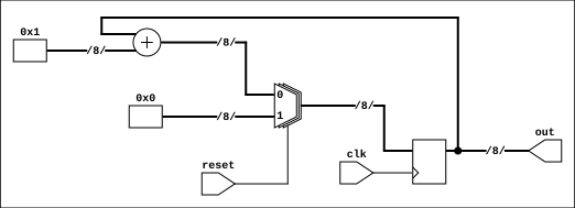
In the counter module I have added two outputs:
out_nb: the output for the nonblocking incrementationout_b: the output for the blocking incrementation
When running the code and reading the waveform we find no difference between out_nb and out_b. Let’s look at the debug output and compare them.
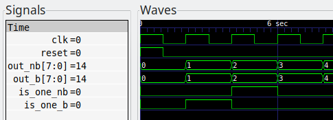
Active:   NB-OUT:   x, B-OUT:   x                    0
Postpone: NB-OUT:   0, B-OUT:   0                    0
------------------------------------------------------
Active:   NB-OUT:   0, B-OUT:   1                    2
Postpone: NB-OUT:   1, B-OUT:   1                    2
------------------------------------------------------
Active:   NB-OUT:   1, B-OUT:   2                    4
Postpone: NB-OUT:   2, B-OUT:   2                    4
...
On the left column we read in what region the code was executed. For showing a output in the active events queue I used the $display directive. For showing a output in the postponed events queue I used the $strobe directive. (See 4.) I would like to remind the reader that the postponed queue is processed after nonblocking assignment updates.
On the right most column we read the time. In between we have the values of the output that was either assigned with a nonblocking assignment or with a blocking one.
So we see that the waveform displays only the value after the simulator passed through all the regions. We know that regardless if we are using <= or = we can count that at the end of each time step the value of out_* will be the same, in this example.
If the values are in the end the same, what is the difference? Check the following two statements out. (Where buff_* is the internal register holding the value corresponding to the respective output.)
buff_out_nb <= buff_out_nb + 8'd1;
buff_out_b = buff_out_b + 8'd1;

buff_is_one_nb <= (buff_out_nb == 8'd1);
buff_is_one_b  <= (buff_out_b == 8'd1);
Note: Both buff_is_one_* could have been updated using = with no practical difference, the problem does not arise from there.
But if you look in the anterior waveform, you see that is_one_nb and is_one_b differ, the former “lagging” with one clock period. Why is this?
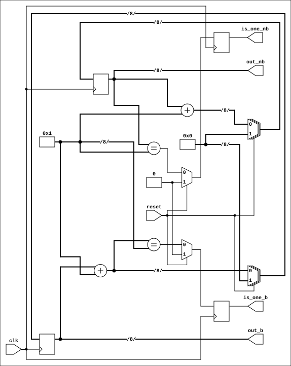
Explanation
TL;DR. The “lagging” is caused by right hand side terms that are evaluated before updates of the left hand side of nonblocking assignments.
As we see in this schematic the circuits for out_nb and out_b are the same. Note that a clock cycle should be longer than the delay on the critical path (the delay from the adder + comparator + multiplexer).
At each tick buff_out_* is incremented. That change will be seen on a posedge. Notice that out_* is not updated as soon as the incrementation finishes. It is only updated on a posedge!
We are unaware of any internal changes just by looking at out_*. By increasing the clock frequency (to a certain limit) the output would be refreshed more often and the counter would also count faster.
But keep in mind that the values associated with out_* are whatever comes out their corresponding D flip flops, not the output of a adder. The adder is only a intermediate on the path to the output.
Let’s look how this thinking applies when reading a line of code.
buff_out_nb <= buff_out_nb + 1
So a wrong way to read this would be: “buff_out_nb gets its value incremented at this moment in time”. A better way to read it would be: “buff_out_nb will be updated, at the end of the time step, with a value, that is made up by adding the value of buff_out_nb during this time step and 8'd1 if the reset is not triggered.”.
The comparison corresponding to is_one_nb uses as input the value of out_nb, i.e. the value that is the output of a D flip flop. Now, if you look at out_b in the schematic and trace it to the adder, you will see that out_b + 1 is feed as an input for the comparison corresponding to is_one_b.
On the one hand, during the “procedures” of a step, is_one_nb uses the value of out_nb (and not the scheduled to be updated value) as it’s input. On the other hand, is_one_b uses an intermediate calculation, that is out_b + 1 as it’s input.
But here comes the comes the catch! If in the simulation the value of out_b can be immediately updated, in the schematic that is impossible. In order to mimic the simulation, the schematic compensates the lack of immediate updates. How? Instead of using the value out_b for comparison for is_one_b, it uses the value of an intermediate point on the path of out_b.
This explains why only at the next clock cycle can we compare the updated value of out_nb with 8'd1. Contrary to this, either the simulator or the synthesis tool will find a way make it seem that out_b is updated immediately.
(The way Yosys interprets the counter module can be seen in dummy.v.)
Conclusion
Anyone who understood the difference can see that this was actually a article about thinking in Verilog, rather that an unimportant programming quirk.
If you want to easily write Verilog, just follow the guidelines formerly mentioned. Do not expect a register which is assigned with <= to be updated immediately. Do not expect to be able to use the RHS value of that assignment in the same clock cycle. This is why a code that was previously written using only = (which is a bad practice) cannot be easily corrected to respect these guidelines.
If you want to remember the difference between the two, always refer to either the IEEE Verilog Standard or the selected quotes from Cummings’s (see 3) article.Yosys note
Sometimes Yosys replaces blocking assignments in a sequential logic block with nonblocking ones. So the guidelines will help you prevent inconsistencies.